Difference between revisions of "iMX6 Rex 5V power supply modifications"
Jump to navigation
Jump to search
| (10 intermediate revisions by the same user not shown) | |||
| Line 1: | Line 1: | ||
| − | [[Category:iMX6 Rex Development | + | [[Category:iMX6 Rex Development Kit]] |
<!-- --> | <!-- --> | ||
<div style="float:right">__TOC__</div> | <div style="float:right">__TOC__</div> | ||
| − | This procedure shows how to modify iMX6 Rex Development | + | This procedure shows how to modify iMX6 Rex Development Kit to support 5V power supply. |
== iMX6 Rex Base Board == | == iMX6 Rex Base Board == | ||
| − | {| | + | {| |
| − | | [[image: | + | | [[image:iMX6_Rex_Development_Kit-PMIC.jpg|100px]] |
| − | | '''''Note:''''' It is required that the power management unit ISL6236AIRZ is fitted on position U22 | + | | style="vertical-align:top;" | '''''Note:''''' It is required that the power management unit ISL6236AIRZ is fitted on position U22 |
|} | |} | ||
| Line 18: | Line 18: | ||
'''''Important:''''' It is recommended to test the base board without the module first: | '''''Important:''''' It is recommended to test the base board without the module first: | ||
| − | * | + | * Set up and double check the input voltage + VIN to 5 Volts. |
| − | * | + | * Measure other voltage rails if they are set as described in the schematic |
| − | * | + | * The upper green POK LED diode in position D18 should be on (all sources are turned on the iMX6 Rex Base Board) |
| − | <br />To power the board, ATX connector (position J38) usage is recommended | + | <br /><br /> |
| − | + | {| | |
| + | | [[image:iMX6_Rex_Development_Kit-ATX_connector.jpg|200px]] | ||
| + | | style="vertical-align:top;" | '''''Note:''''' To power the board, ATX connector (position J38) usage is recommended | ||
| + | |} | ||
== iMX6 Rex Module == | == iMX6 Rex Module == | ||
| − | '''''Note:''''' It is required that the power management unit ISL6236AIRZ is fitted on positions U11 and U13 | + | {| |
| − | + | | [[image:iMX6_Rex_Development_Kit-PMIC.jpg|100px]] | |
| + | | style="vertical-align:top;" | '''''Note:''''' It is required that the power management unit ISL6236AIRZ is fitted on positions U11 and U13 | ||
| + | |} | ||
=== Bottom side modifications === | === Bottom side modifications === | ||
[[image:iMX6_Rex_Module-5V_modification_bottom.jpg|800px]] | [[image:iMX6_Rex_Module-5V_modification_bottom.jpg|800px]] | ||
Latest revision as of 22:52, 26 October 2021
This procedure shows how to modify iMX6 Rex Development Kit to support 5V power supply.
iMX6 Rex Base Board
|
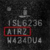
Note: It is required that the power management unit ISL6236AIRZ is fitted on position U22 |
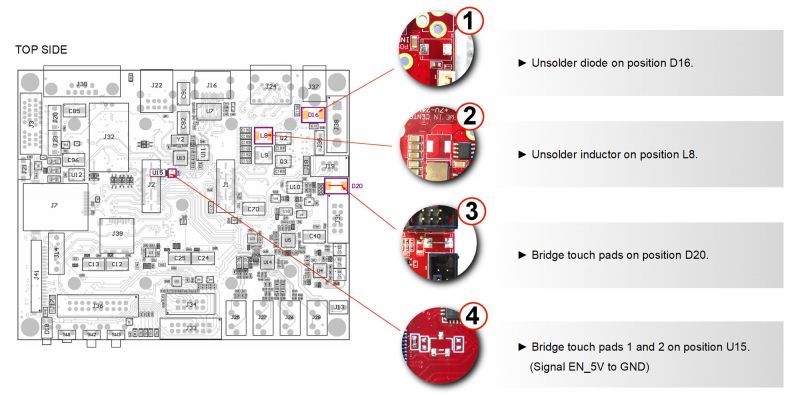
Top side modifications
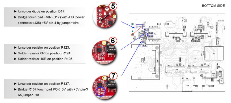
Bottom side modifications
Important: It is recommended to test the base board without the module first:
- Set up and double check the input voltage + VIN to 5 Volts.
- Measure other voltage rails if they are set as described in the schematic
- The upper green POK LED diode in position D18 should be on (all sources are turned on the iMX6 Rex Base Board)
|
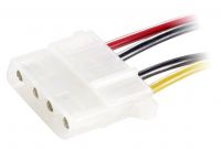
Note: To power the board, ATX connector (position J38) usage is recommended |
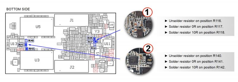
iMX6 Rex Module

|
Note: It is required that the power management unit ISL6236AIRZ is fitted on positions U11 and U13 |
