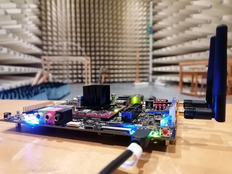
iMX8M Industrial EMC testing
Electromagnetic compatibility results for iMX8M Industrial Development Kit are shown on this page. Test setup and scripts are described in details.
These measurement were performed with boards using the actual hardware and software configuration of the web shop development kits.
Connected cables/devices
- Power jack: +5V 40W power supply was used for input voltage. Power supply PN: TR9WA8000CCPIM(R6B)
- SD card (Sandisk): preloaded with filesystem, used for booting and for read/write test
- Ethernet: 1 meter CAT Ethernet loopback cable connected. Forced to 100Mb and used for ping test
- DisplayPort (M) input source and monitor used: Output signal is connected to monitor through 2m DisplayPort cable, monitor is plugged into mains but not turned on. Monitor laid flat on the floor to minimise its affect on results. Used LCD monitor: 29" LG UltraWide 29WP60G-B 2560 × 1080 px
- LCD Display:Capacitive touch panel + Graphic LCD Display Module 1024 x 600 resolution. LCD PN: NHD-10.1-1024600MB-LSXV-CTP
- 2x USB flash drive: SanDisk Ultra Flair 16GB USB 3.2 Gen 1 (USB 3.0), USB-A each connected through a 1m USB 3.2 Gen extension cable (Molex PN: 0687890035). Both used during read/write test
- USB-C: Connected USB-C extension cable + USB stick. Cable PN: FCR72003. USB-C stick description: Kingston DataTraveler 80 32 GB USB stick USB 3.2 Gen 1 (USB 3.0), USB-C
- PCAM 5C: 5 MP camera module Camera PN:410-358. The camera was plugged to baseboard and recognized by kernel, no future communication. During EMC measurement was added ferrite ring at flex cable close to camera module. Ferrite ring PN:SRP33.5x6.5x10
- CAN: MCP2518FD module inserted, but not actively used. No cable connected
- Wi-Fi and Bluetooth: SPB228-D-3 or CM-276NF Populated on module (depend on configuration) inserted, but not actively used. Two ntennas connected
- Debug cable: FTDI TTL-3V3 UART to USB cable, used only to setup the board, not used and not plugged in during the measurements
- Microphone: Microphone connected but not actively used.
- Headphones: Headphones connected but not actively used.
- Line Out: Line Out connected but not actively used.
Test description
The main purpose of testing was to measure Radiated emission of iMX8M Industrial Development Kit performing under heavy load. Following threads were running during the measurements:
- CPU stress test
- Memory stress test
- DisplayPort output
- SD card test (read & write)
- 2x USB 3.0 test (USB memory drive read & write stress test)
- Ethernet ping (and Ethernet SSH session)
Results
All the results were measured in compliance with the emission limits for FCC Class B (EMC standard EN 55032B). Class B devices are suitable for both residential and industrial applications as the norm standards use more restrictive limits.
Graph description
Lower band 30MHz - 1GHz
Radiated emission is measured and displayed as quasi-peak values. This relation is represented as a green curve in the measurements. Class B limits are shown by red highlighted line.
For measurements was used Bilog antenna CBL6112A 30 MHz to 2Ghz
Higher band 1GHz - 6GHz
Two plots displaying the power density are used to show results in higher bands. Similar to lower frequencies a green curve represents quasi-peak values. Class B limits applied for quasi-peak measurements is plotted as the higher placed red line .
For measurements was used Double-Ridged Waveguide Horn Antenna 1 GHz - 18 GHz
iMX8M Industrial Development Kit, MAX-Quad-Industrial module no:6 PASS
Test description:
- stressapptest for CPU and memory
- Ethernet loopback
- DisplayPort output tested with Full HD 2560 × 1080
- Ethernet ping test
This setup used HDMI option with separate video input source and monitor. Both the board and the monitor were placed on the floor to minimise its effects. The power source was hidden inside the chamber tunnel under the testing table.
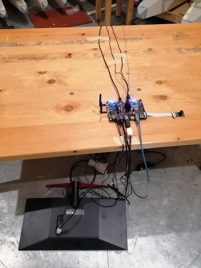
Vertical + Horizontal polarisation
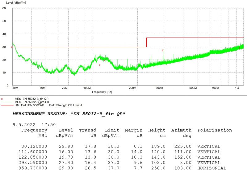
iMX8M Industrial Development Kit, MAX-Quad-Industrial module no:6: 30MHz - 1GHz
Vertical + Horizontal polarisation
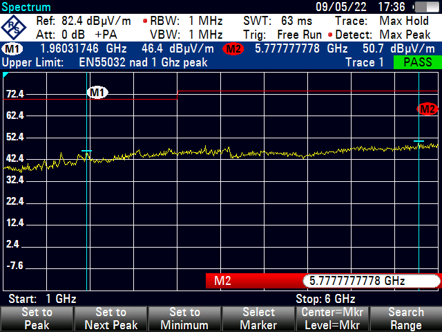
iMX8M Industrial Development Kit, MAX-Quad-Industrial module no:6: 1GHz - 6GHz
Running the script
Plug the board into mains and connect to it via console and copy code below
for a in $(seq 1 1 999)
do
	for b in $(seq 1 1 999)
	do
		for c in $(seq 1 1 99)
		do
			for d in $(seq 1 1 99)
			do
				uptime
				echo "Test $a Test $b Test $c  $d times"
				echo "Start stress-ng --iomix 1 -t 10 -v"
				stress-ng --iomix 1 -t 10 -v
				echo "End"
				echo "Start Thermal zone information"
				stress-ng --matrix 0 --tz -t 10 --log-brief -t 10
				echo "End"
				ping -q -c1 192.168.0.2 >> env-chamber-testing.log
				  if [ $? -ne 0 ]
				  then
					echo "$(date +\%Y/\%m/\%d-\%T)($(date +\%Z)) ERROR: Ping failed"
				  fi
				echo "End"
			done
		done
	done
done
iMX8M Industrial Development Kit Modul 2 and external LCD – PASS
Test description:
- stressapptest for CPU and memory
- Ethernet loopback
- 2x USB 3.0 A
- Audio
- USB-C
- running heavy testing script for USB and SD card read/write test
- LCD Newhaven LVDS Capacitive Display Set
These results show that a heavy loaded iMX8M Industrial Development Kit complies with stricter regulation even if no enclosure is used.
800px
Vertical + Horizontal polarisation
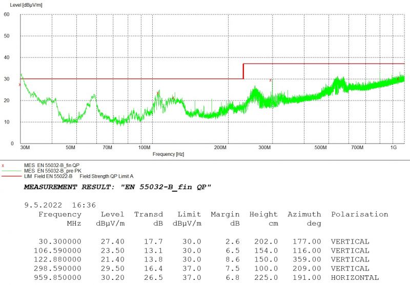
iMX8M Industrial NH LVDS LCD USB Audio Camera Module 2: 30MHz - 1GHz
Vertical + Horizontal polarisation
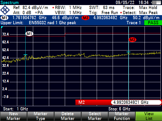
iMX8M Industrial NH LVDS LCD USB Audio Camera Module 2: 1GHz - 6GHz
Conducted Emissions
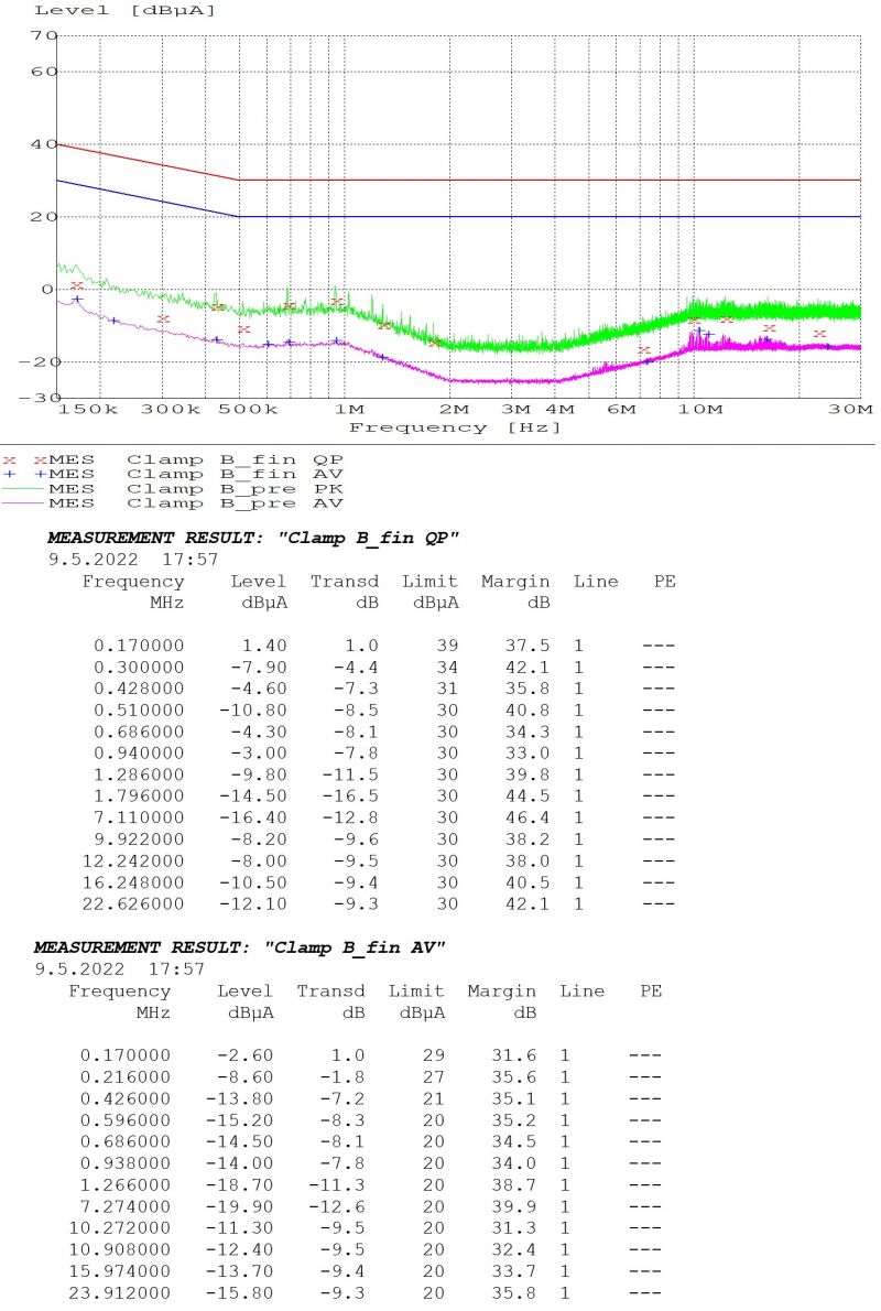
iMX8M Industrial NH LVDS LCD Module 2: 150kHz - 30MHz
iMX8M Industrial Development Kit + Module No:6 – PASS
Test description:
- Testing only iMX8M Industrial Development Kit + Module No:6
- stressapptest for CPU
- stressapptest for memory
Vertical + Horizontal polarisation
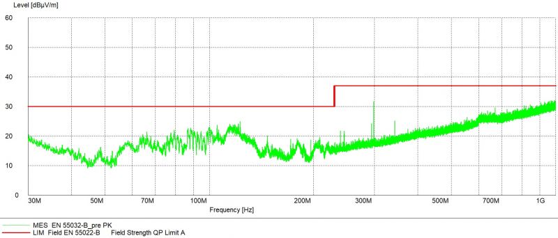
iMX8M Industrial Development Kit, MAX-Quad-Industrial module no:6: 30MHz - 1GHz
Conducted Emissions
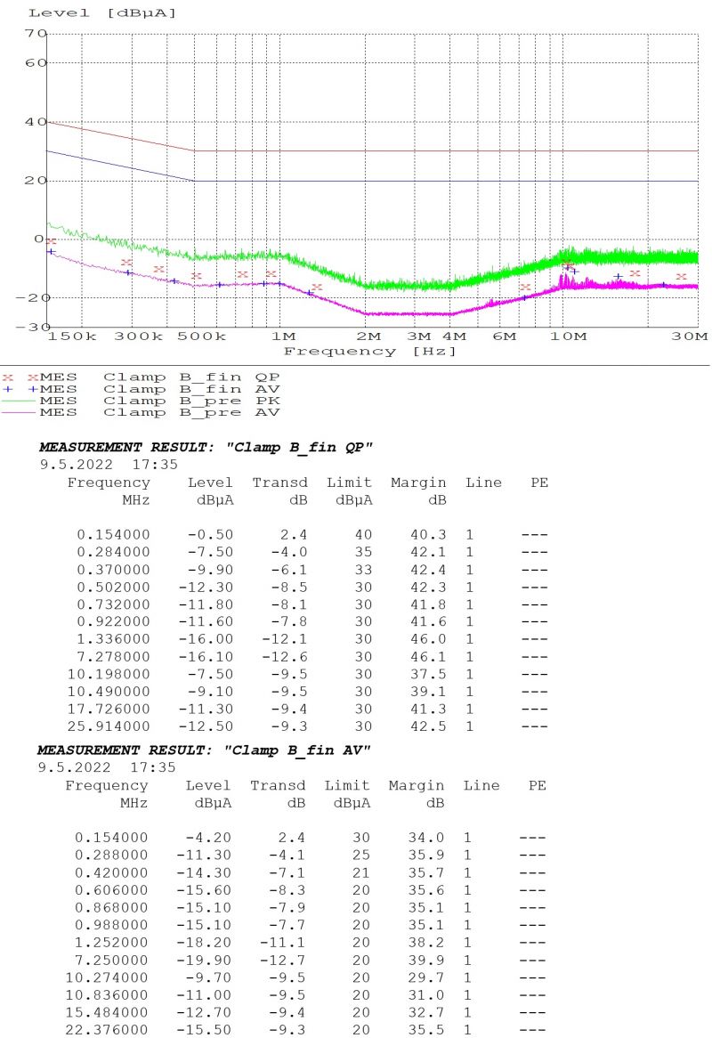
iMX8M Industrial Development Kit + Module No:6
free
Preparing the test
Boot device and software
SD card was selected as a booting device for all the boards. U-Boot settings were not adjusted as the default configuration was used. The only change compared to standard software package was running a multimedia filesystem. To prepare a fresh SD card follow these instructions. Here is an example of creating a SD card suitable for Max configuration:
git clone https://github.com/voipac/imx6tinyrex_bin_linux
cd imx6tinyrex_bin_linux/
sudo ./fsl-sdcard-partition.sh -max /dev/mmcblk0
Starting DHCP server
The boards were mainly operated through SSH sessions. Thus it is very useful to have the same IP address during the whole process. The easiest way to do so is to run DHCP server on the controlling computer. To allow boards using the same address enable persistent leases with a long duration (2880 min used below):

Preserving SSH session
To minimise the possibility of results being affected, the control computer was disconnected and taken outside of the test chamber (after the board was setup).
When Ethernet cable connected to a board is disconnected, Linux terminates all the processes started within SSH sessions by default. Screen command allows to keep these sessions running. This command allow tasks to continue even if the cable is unplugged (and Ethernet loopback is plugged right away). It is important to make sure the filesystem includes this command:
sudo apt-get install screen
Running the script
Plug the board into mains and connect to it via SSH session. Screen environment is opened:
screen -S tinyrex
Testing scripts command consists of following arguments
- the first parameter - version of tested board (-max, -pro or -basic)
- the second parameter - USB drive 1 location
- the third parameter - USB drive 2 location
- the fourth parameter - SD card location
Several commands which were used during EMC testing are shown below:
- iMX8MQ Development Kit Pro:
./imx8mq-voipac-peripheral-test.sh -pro sda1 sdb1 mmcblk1p1 | tee -i imx8mq-emc-testing.log
- iMX8MQ Development Kit Max:
./imx8mq-voipac-peripheral-test.sh -max sda1 sdb1 mmcblk1p1 | tee -i imx8mq-emc-testing.log
- iMX8MQ Development Kit Basic:
./imx8mq-voipac-peripheral-test.sh -basic -n sda1 sdb1 mmcblk1p1 | tee -i imq8mq-emc-testing.log
The complete script can be found in [1]
