i.MX25 SODIMM PC Flashing images with Advanced Toolkit
This page show an alternative option how to program Linux binaries into i.MX25 SODIMM PC Modules compared to the default flashing using Barebox and TFTP server. Advanced ToolKit Platform is used during this process while running on Windows XP operating system. Newer versions of Windows OP (including Windows 10) are supported utilizing CEDownloader program.
Preparing the host computer
Installing Advanced ToolKit
The Advanced ToolKit package can be obtained from the download section. Unpack and install the executable file FSL_ATK_TOOL_WINS_STD_INSTALL_1_70.exe. This package also contains detailed documentation concerning the program usage.
Computer reboot after installation is not required. Open and run the program.
Initilization of USB driver
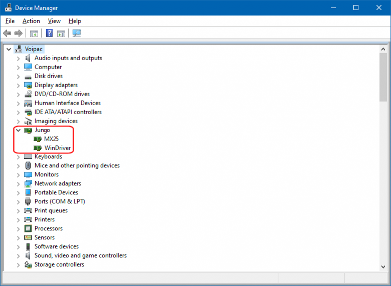
During the install procedure, the USB drivers are installed automatically. To verify that the driver is ready for usage, plug in the board using USB mini cable and navigate to the Device Manager. When the hardware is attached to the computer properly, device named Jungo appears in the list:

Note: In case the USB driver was not installed successfully, it can be loaded manually by starting wd_install_4NT.bat batch file located in <TOOL_INSTALL_PATH>/windriver/ directory. The same folder also contains bat file wd_uninstall_4NT.bat for uninstalling the driver. Older versions of the USB driver can also be uninstalled using the toolkit utility.
Preparing the development board
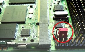
Serial Boot option selected by H902 (BOOTMODE) jumper is required. To do so use a link between pins 2 and 3:

|

|
| Serial Boot | Direct Boot |
At this moment i.MX25 SODIMM PC - Development Kit will not boot from the stored binary but wait in the serial mode. Connect the board and the host computer with USB mini cable. Power on the board.
Configuring Advanced ToolKit feature
Start Advanced ToolKit program. Upon start set up the settings following this example:

Configuration required for i.MX25 SODIMM PC - Development Kit:
- Select i.MX25_TO1.1 as CPU option
- Choose Custom Initial File for memory initiation. Files prepared for i.MX25 SODIMM PC Module are located within the feature package
- Select USB option as the host communication channel
- Leave 'Bypass the settings' unchecked otherwise the current setup will be ignored
Click Next to finish the configuration. Advanced ToolKit dialog window is shown only if the development kit was connected correctly and the communication was established.
Flashing details and modes of operation
All the program possibilities to communicate with the board can be accessed in Flash tool section. This toolkit enables images to be downloaded, programmed, dumped or erased.
Select Flash Tool option and continue with Go button:

Upon opening the following screen is displayed:

This working environment consists of multiple options. These values are especially important for i.MX25 SODIMM PC - Development Kit setup:
- Operation Type selects four actions to be performed. Additional four check boxes further customize the operation. Two of them are especially important during programming:
- BI Swap is the option used for Windows Embedded CE images
- BBT is chosen in case of Linux images to be flashed
- Flash Model field determines supported Flash memories:
- NAND memories with starting address to be 0x00000000
- MMC/SD devices with available space to start at 0x00000000
- Image Field chooses a file for programming, downloading and dumping
All options are described in the table below:
| Section | Option | Description |
|---|---|---|
| Operation type | Download | Downloads the image to the address specified, and then executes directly at the
downloaded address. |
| Dump | Dumps a selected area of Flash device to a file. | |
| Program | Programs a selected area of Flash from a file. | |
| Erase | Erases a selected area of Flash. | |
| BI Swap | Swaps Bad block identifier data, which is one solution for Bad block identifier data in the case that Nand Flash is incompatible with Nand Flash Controller. | |
| BBT | Bad block Table, which is the table recording all bad block information. | |
| Interleave | The are two kind of access mode when they are multiple nand flash chips on board, for example, 4 chips on board. | |
| LBA | Logic Block Address, which indicates that the input address is a logic block address if it is checked. This option is only used on wince platform, for Linux, it should be ignored. | |
| Read Back Check | Comparing the programmed data with original data in programming process will not be done to speed up the programming speed if this option is un-checked. The option will be visible only when programming option is selected. By default, this option is checked. | |
| Flash Device | Flash Model | Click the down arrow to select the Flash type for the associated board when the Program, Dump, or Erase Flash operations are selected. |
| Flash Lib | Device program running on the board that handles the communication with the PC host through the protocol to program/dump/erase the flash. | |
| Operation Settings | Address | The address in the physical memory of the target board where the operation will start. |
| Size | Size in bytes for erase and dump operations. | |
| Image | Image file | For downloading operations, indicates the image to be downloaded to RAM. For Flash operations, indicates the image to be downloaded to Flash. For dumping operations, indicates the file that is used to store the dumped content. |
| Process | Progress bar | Displays the completed percent of the selected operation. |
| Information Log | Displays the execution log. |
Storage media partitioning
Note: Make sure that all the valuable information were downloaded prior the start of programming as the flashing procedure also consists of erasing the memory.
Linux based systems (including Android) use BBT option to handle bad memory blocks. Storage media is partitioned in this format:
| Address | Size | File | Note |
|---|---|---|---|
| 0x0000 0000 | 0x0004 0000 | Barebox.bin | Kernel bootloader |
| 0x0004 0000 | 0x0002 0000 | Bootloader | Environment |
| 0x0006 0000 | 0x002A 0000 | zImage.bin | Linux kernel |
| 0x0030 0000 | - | rootfs.bin | Root filesystem |
Flashing images
Flashing bootloader to address 0x00000000:

Flashing Kernel image to address 0x00060000:

Filesystem is flashed to address 0x00300000:

After all three images were programmed successfully, turn off the board and change the H902 jumper (BOOTMODE) to select the direct boot. Change the jumper link to connect pins 1 and 2 together.
Open a terminal session in the host computer with these settings:
- Speed (baud): 115200
- Data bits: 8
- Stop bits: 1
- Parity: None
- Flow control: None
Turn on the board and and set MAC Address shown on the module label. The MAC Address must be set in a format including colons: 00:0d:15:00:XX:XX.

Boot up the board. The default vmx25 login is root.
