Difference between revisions of "iMX91 Industrial Flashing Procedure"
Jump to navigation
Jump to search
| Line 19: | Line 19: | ||
=== Windows === | === Windows === | ||
* Go to: https://github.com/NXPmicro/mfgtools/releases | * Go to: https://github.com/NXPmicro/mfgtools/releases | ||
| − | * Select the latest stable release.<br />Example: '''''Releases/uuu_1.5. | + | * Select the latest stable release.<br />Example: '''''Releases/uuu_1.5.233''''': https://github.com/nxp-imx/mfgtools/releases/tag/uuu_1.5.233 |
| − | * Download: [https://github.com/nxp-imx/mfgtools/releases/download/uuu_1.5. | + | * Download: [https://github.com/nxp-imx/mfgtools/releases/download/uuu_1.5.233/uuu.exe uuu.exe] |
* Save the file into: C:\uuu | * Save the file into: C:\uuu | ||
== Preparing the binaries == | == Preparing the binaries == | ||
| − | * Download the default WIC filesystem image e.g. for pro configuration: [https://downloads.voipac.com/files/iMX91_Industrial_Development_Kit/module/software/filesystem/voipac-image- | + | * Download the default WIC filesystem image e.g. for pro configuration: [https://downloads.voipac.com/files/iMX91_Industrial_Development_Kit/module/software/filesystem/voipac-image-imx91-pro.rootfs.wic voipac-image-imx91-pro.rootfs.wic] |
== Flashing procedure == | == Flashing procedure == | ||
| Line 31: | Line 31: | ||
* Plug USB Micro-B cable to baseboard CONSOLE connector and PC<br />'''''Note:''''' Make sure that UART1 and UART2 jumpers are in CP2105 positions (USB/UART bridge).<br /> | * Plug USB Micro-B cable to baseboard CONSOLE connector and PC<br />'''''Note:''''' Make sure that UART1 and UART2 jumpers are in CP2105 positions (USB/UART bridge).<br /> | ||
| − | [[image:iMX Development Baseboard-Serial console jumpers- | + | [[image:iMX Development Baseboard-Serial console jumpers-iMX91 COM.png|594px]]<br /><br /> |
* Plug USB-C cable to baseboard USB-C connector and PC<br />'''''Note:''''' Powering of the development kit is not required during the flashing procedure.<br />'''''Note:''''' After connecting 2 development board cables, 2 serial ports named ''Silicon Labs CP210x USB to UART Bridge'' should appear in the controlling PC.<br /> | * Plug USB-C cable to baseboard USB-C connector and PC<br />'''''Note:''''' Powering of the development kit is not required during the flashing procedure.<br />'''''Note:''''' After connecting 2 development board cables, 2 serial ports named ''Silicon Labs CP210x USB to UART Bridge'' should appear in the controlling PC.<br /> | ||
| Line 45: | Line 45: | ||
==== Linux ==== | ==== Linux ==== | ||
<syntaxhighlight lang="bash"> | <syntaxhighlight lang="bash"> | ||
| − | sudo ./uuu -b emmc_all voipac-image- | + | sudo ./uuu -b emmc_all voipac-image-imx91-max.rootfs.wic |
</syntaxhighlight> | </syntaxhighlight> | ||
==== Windows ==== | ==== Windows ==== | ||
<syntaxhighlight lang="bash"> | <syntaxhighlight lang="bash"> | ||
| − | uuu.exe -b emmc_all voipac-image- | + | uuu.exe -b emmc_all voipac-image-imx91-max.rootfs.wic |
</syntaxhighlight> | </syntaxhighlight> | ||
| Line 57: | Line 57: | ||
==== Linux ==== | ==== Linux ==== | ||
<syntaxhighlight lang="bash"> | <syntaxhighlight lang="bash"> | ||
| − | sudo ./uuu -b sd_all voipac-image- | + | sudo ./uuu -b sd_all voipac-image-imx91-max.rootfs.wic |
</syntaxhighlight> | </syntaxhighlight> | ||
==== Windows ==== | ==== Windows ==== | ||
<syntaxhighlight lang="bash"> | <syntaxhighlight lang="bash"> | ||
| − | uuu.exe -b sd_all voipac-image- | + | uuu.exe -b sd_all voipac-image-imx91-max.rootfs.wic |
</syntaxhighlight> | </syntaxhighlight> | ||
| Line 73: | Line 73: | ||
C:\Users\voipac>cd c:\uuu | C:\Users\voipac>cd c:\uuu | ||
| − | c:\uuu>uuu.exe -b emmc_all voipac-image- | + | c:\uuu>uuu.exe -b emmc_all voipac-image-imx91-pro.rootfs.wic |
| − | uuu (Universal Update Utility) for nxp imx chips -- libuuu_1. | + | uuu (Universal Update Utility) for nxp imx chips -- libuuu_1.5.233-0-g79ce7d2 |
Success 1 Failure 0 | Success 1 Failure 0 | ||
| Line 85: | Line 85: | ||
| − | [[image: | + | [[image:iMX91_Industrial_Development_Kit-Flashing_binaries.png|750px]] |
==== Serial console ==== | ==== Serial console ==== | ||
| Line 107: | Line 107: | ||
Flashing Sparse Image | Flashing Sparse Image | ||
........ wrote 16776192 bytes to 'all' | ........ wrote 16776192 bytes to 'all' | ||
| − | Starting download of | + | Starting download of 14886964 bytes |
.......................................................................... | .......................................................................... | ||
| − | ............. | + | ....................................... |
| − | downloading of | + | downloading of 14886964 bytes finished |
writing to partition 'all' | writing to partition 'all' | ||
sparse flash target is mmc:0 | sparse flash target is mmc:0 | ||
| − | writing to partition 'all' for sparse, buffer size | + | writing to partition 'all' for sparse, buffer size 14886964 |
Flashing sparse image at offset 0 | Flashing sparse image at offset 0 | ||
Flashing Sparse Image | Flashing Sparse Image | ||
| − | ........ wrote | + | ........ wrote 14886912 bytes to 'all' |
| − | Starting download of | + | Starting download of 1470464 bytes |
| − | + | ........... | |
| − | downloading of | + | downloading of 1470464 bytes finished |
writing to partition 'bootloader' | writing to partition 'bootloader' | ||
Initializing 'bootloader' | Initializing 'bootloader' | ||
| Line 126: | Line 126: | ||
Writing 'bootloader' | Writing 'bootloader' | ||
| − | MMC write: dev # 0, block # 0, count | + | MMC write: dev # 0, block # 0, count 2872 ... 2872 blocks written: OK |
Writing 'bootloader' DONE! | Writing 'bootloader' DONE! | ||
Detect USB boot. Will enter fastboot mode! | Detect USB boot. Will enter fastboot mode! | ||
Detect USB boot. Will enter fastboot mode! | Detect USB boot. Will enter fastboot mode! | ||
| − | |||
</syntaxhighlight> | </syntaxhighlight> | ||
| Line 145: | Line 144: | ||
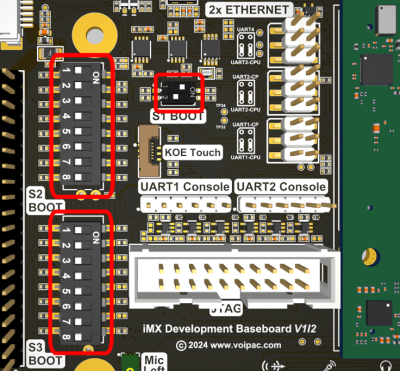
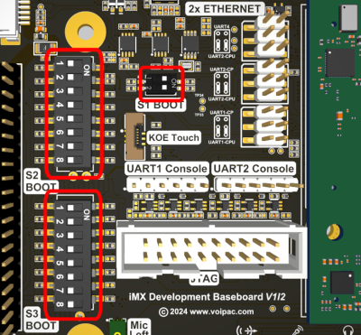
* Make sure that S2 BOOT and S3 BOOT DIP switches are in correct positions in order to boot from the selected storage media (eMMC Flash memory or SD Card): | * Make sure that S2 BOOT and S3 BOOT DIP switches are in correct positions in order to boot from the selected storage media (eMMC Flash memory or SD Card): | ||
==== eMMC Flash Memory boot (default) ==== | ==== eMMC Flash Memory boot (default) ==== | ||
| − | [[File:boot eMMC | + | [[File:boot eMMC iMX91.png|400px]] <br /><br /> |
==== SD Card boot ==== | ==== SD Card boot ==== | ||
| − | [[File:boot SD Card | + | [[File:boot SD Card iMX91.png|400px]]<br /><br /> |
* Connect USB Micro-B debug cable, switch on the power and the development kit starts booting with the new binaries<br /><br /> | * Connect USB Micro-B debug cable, switch on the power and the development kit starts booting with the new binaries<br /><br /> | ||
| Line 161: | Line 160: | ||
</syntaxhighlight> | </syntaxhighlight> | ||
| − | * Use these commands to set a DTB file for the image loaded in SD Card (example for | + | * Use these commands to set a DTB file for the image loaded in SD Card (example for Tianma Display): |
<syntaxhighlight lang="bash"> | <syntaxhighlight lang="bash"> | ||
u-boot=>fatls mmc 1:1 | u-boot=>fatls mmc 1:1 | ||
| − | u-boot=>setenv fdtfile | + | u-boot=>setenv fdtfile imx91-11x11-evk-tianma-wvga-panel.dtb |
u-boot=>saveenv | u-boot=>saveenv | ||
</syntaxhighlight> | </syntaxhighlight> | ||
| − | [[File: | + | [[File:imx91_dtb_setting.png|740px]]<br /><br /> |
* To boot the image, reset the board or type the boot command: | * To boot the image, reset the board or type the boot command: | ||
Revision as of 11:11, 30 October 2025
This page describes how to flash binaries into iMX91 Industrial Module's eMMC Flash memory or into SD card that is located on the iMX Development Baseboard.
Note: All of the steps listed below are NOT REQUIRED for standard configuration modules and development kits.
Installing Universal Upload Utility (UUU)
Linux
git clone https://github.com/NXPmicro/mfgtools.git
cd mfgtools
mkdir .build && cd .build && cmake .. && make -j`nproc`
The binary called uuu, which is used for flashing, is located in .build/uuu directory.
Windows
- Go to: https://github.com/NXPmicro/mfgtools/releases
- Select the latest stable release.
Example: Releases/uuu_1.5.233: https://github.com/nxp-imx/mfgtools/releases/tag/uuu_1.5.233 - Download: uuu.exe
- Save the file into: C:\uuu
Preparing the binaries
- Download the default WIC filesystem image e.g. for pro configuration: voipac-image-imx91-pro.rootfs.wic
Flashing procedure
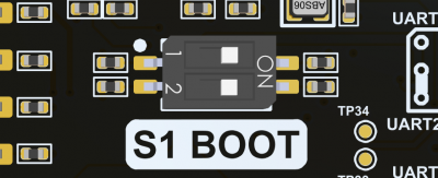
- Set serial downloader mode by sliding DIP switch S1 BOOT positions to: 1-OFF, 2-ON
- Plug USB Micro-B cable to baseboard CONSOLE connector and PC
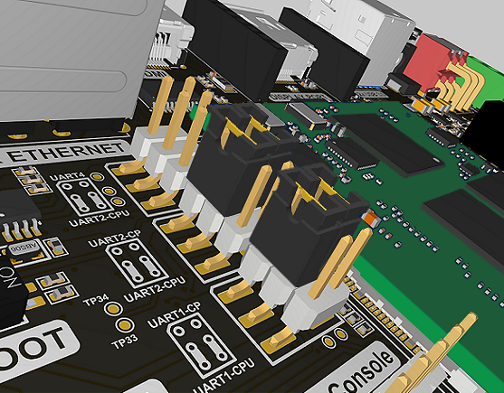
Note: Make sure that UART1 and UART2 jumpers are in CP2105 positions (USB/UART bridge).
- Plug USB-C cable to baseboard USB-C connector and PC
Note: Powering of the development kit is not required during the flashing procedure.
Note: After connecting 2 development board cables, 2 serial ports named Silicon Labs CP210x USB to UART Bridge should appear in the controlling PC.
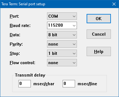
- Default Serial Port Settings
- Download and copy imx-boot and *.wic files into uuu\ directory
- Choose one of the following commands to start the flashing process:
eMMC Flash Memory (default)
Linux
sudo ./uuu -b emmc_all voipac-image-imx91-max.rootfs.wic
Windows
uuu.exe -b emmc_all voipac-image-imx91-max.rootfs.wic
SD Card
Linux
sudo ./uuu -b sd_all voipac-image-imx91-max.rootfs.wic
Windows
uuu.exe -b sd_all voipac-image-imx91-max.rootfs.wic
Flashing logs
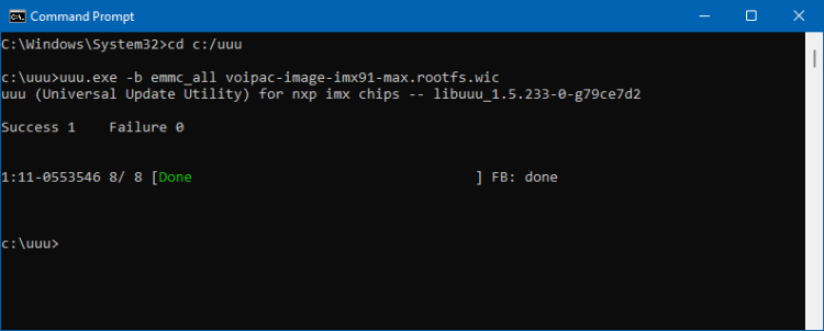
UUU
Microsoft Windows [Version 10.0.19045.2486]
(c) Microsoft Corporation. All rights reserved.

C:\Users\voipac>cd c:\uuu

c:\uuu>uuu.exe -b emmc_all voipac-image-imx91-pro.rootfs.wic
uuu (Universal Update Utility) for nxp imx chips -- libuuu_1.5.233-0-g79ce7d2

Success 1    Failure 0


2:43     8/ 8 [Done                                  ] FB: done

c:\uuu>
Serial console
.....................................................
downloading of 16776244 bytes finished
writing to partition 'all'
sparse flash target is mmc:0
writing to partition 'all' for sparse, buffer size 16776244
Flashing sparse image at offset 0
Flashing Sparse Image
........ wrote 16776192 bytes to 'all'
Starting download of 16776244 bytes
..........................................................................
.....................................................
downloading of 16776244 bytes finished
writing to partition 'all'
sparse flash target is mmc:0
writing to partition 'all' for sparse, buffer size 16776244
Flashing sparse image at offset 0
Flashing Sparse Image
........ wrote 16776192 bytes to 'all'
Starting download of 14886964 bytes
..........................................................................
.......................................
downloading of 14886964 bytes finished
writing to partition 'all'
sparse flash target is mmc:0
writing to partition 'all' for sparse, buffer size 14886964
Flashing sparse image at offset 0
Flashing Sparse Image
........ wrote 14886912 bytes to 'all'
Starting download of 1470464 bytes
...........
downloading of 1470464 bytes finished
writing to partition 'bootloader'
Initializing 'bootloader'
switch to partitions #1, OK
mmc0(part 1) is current device
Writing 'bootloader'

MMC write: dev # 0, block # 0, count 2872 ... 2872 blocks written: OK
Writing 'bootloader' DONE!
Detect USB boot. Will enter fastboot mode!
Detect USB boot. Will enter fastboot mode!
Running the newly flashed binaries
After completing the above steps, eMMC Flash memory or SD Card is flashed and the following steps are to be performed to boot the new image:
- Unplug USB-C cable from PC
- Set Boot mode by sliding DIP switch S1 BOOT positions to: 1-ON, 2-OFF
- In case of SD card boot set DIP switch S1 BOOT positions to 1-ON, 2-ON
- Make sure that S2 BOOT and S3 BOOT DIP switches are in correct positions in order to boot from the selected storage media (eMMC Flash memory or SD Card):
eMMC Flash Memory boot (default)
SD Card boot
- Connect USB Micro-B debug cable, switch on the power and the development kit starts booting with the new binaries
Setting DTB file
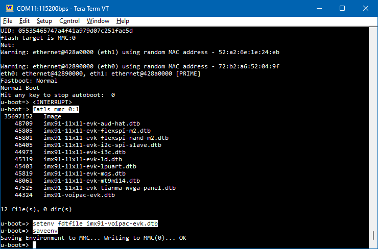
- To set a correct DTB file, stop autoboot.
- Use these commands to set a DTB file for the image loaded in eMMC:
u-boot=>fatls mmc 0:1
u-boot=>setenv fdtfile imx91-voipac-evk.dtb
u-boot=>saveenv
- Use these commands to set a DTB file for the image loaded in SD Card (example for Tianma Display):
u-boot=>fatls mmc 1:1
u-boot=>setenv fdtfile imx91-11x11-evk-tianma-wvga-panel.dtb
u-boot=>saveenv
- To boot the image, reset the board or type the boot command:
u-boot=>boot

